High-Level Car Physics System (C++)

Wheeled vehicles are widely used in various simulations. The high-level Car Physics system, implemented as a set of C++ components, is indended to simplify creation of realistic wheeled vehicles in UNIGINE. It minimizes efforts required to create virtually any wheeled vehicle, be it a 4WD SUV, an exploration rover, or a sophisticated multi-axle transporter.
The following features are available:
- Setting engine's power and resistance curves, as well as idle speed (RPM)
- Gearbox simulation (manual and automatic) enabling you to adjust throttle an speed values for shifting gears along with transition time, as well as to set the number of gears and configure gear ratios
- Mathematical wheel model for more realistic steering, enabling simulation of forces affecting the rotating wheel, along with an ability to adjust suspension travel distance, spring, and damping values
- Easy setup of steering and driving axes along with capability to turn the differential lock on and off
- A set of debug windows displaying information on all vehicle parameters in real time
- Switching between different views (driver's, external camera, etc.)
- Simulation of various surface conditions (such as dry, wet, snow-covered, or icy road, mud, and so on)
Instructions given below cover the process of creation of a wheeled vehicle using the Vehicle Sample from the SDK in a new blank project. The step-by-step guide will take you through the process of creating all necessary nodes and configuring component parameters you need to have a functional vehicle, assuming that you have at your disposal a model of the vehicle's body and models of its wheels.
See also#
- The C++ Component System article to learn more about implementing logic in C++ using components.
- The Vehicle Sample from the suite of C++ Samples demo included in the SDK.
Step 1. Prepare a Project#
First, we should prepare a project and get all necessary source-files containing implementation of components from the sample. So, we perform the following actions:
- Create a new C++ project.
- Enable the Custom C++ Component System feature.

- Open your new project's source folder and create a new vehicle_components folder in it.
- Then, open the source/vehicle_sample folder and copy all the files it contains to the vehicle_components folder, that you've just created.
- Open your project in your IDE and add all source files from the vehicle_components folder to it.
- Add initialization code for the Custom C++ Component System to the AppSystemLogic::init() method:
Source code (C++)
#include "ComponentSystem/ComponentSystem.h" /* ... */ int AppSystemLogic::init() { /* ... */ // initialize ComponentSystem and register all components ComponentSystem::get()->initialize(); /* ... */ } - Build and run your project to register all components and generate necessary properties. We are going to use these properties later to configure our vehicle. Meanwhile, we can proceed to the next step.
Step 2. Prepare Your Vehicle Model#
Next, we create a model representing the vehicle's body and a model for vehicle's wheels (or several models, depending on how many different types of wheels your vehicle has).
The Y axis of all models (including wheels) should be pointing forward. So, you can't just make a copy of a wheel and rotate it around the Z axis by 180 degrees.

The scale of all models should be equal to 1 along all axes, to ensure correct physics simulation.
Step 3. Create Node Hierarchy#
In order for the system to work, your vehicle's hierarchy should be properly organized. The following hierarchy is recommended:
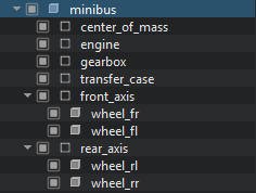
All nodes in the hierarchy, except for the vehicle's body and wheels, are DummyNodes. These dummies serve only to organize the components logic and have an identity transform matrix, except for the center_of_mass, as its position defines the position of the vehicle's center of mass in the local coordinates of the vehicle's body (must have the body as parent).
Step 4. Engage Physics#
Then, we should assign a rigid body to the object representing the vehicle's body and disable the Shape-Based option for it, to turn off automatic calculation as inertia, mass, and center of mass are specified in the component. Then, add necessary number of physical shapes to specify the geometry of the body.

Step 5. Assign and Configure Components#
At this stage we assign component properties generated at Step 1 and configure necessary parameters for the engine, transmission, wheels, etc.
Engine#
Let's start with configuring the engine. Assign the car_engine component to the engine dummy node and specify necessary engine parameters, such as maximum, minumum, and idle rpm values, inertia of moving parts of the transmission and set up dependencies for torque and resistance on rpm.
Gearbox#
Assign the car_gearbox component to the gearbox node. Here we set transmission type (MT or AT), specify all gear numbers and shifting time. This component also controls switching between the gears (AT), so for each gear we should set throttle and speed values for switching up or down to the next gear.

The array of gear values must contain at least 3 elements: neutral, first front, and rear. Tables describing Up and Down switching sequences should have the number of elements equal to the number of transitions: number_of_forward_gears - 1. For example, for a 3-speed gearbox we have:
- 1 -> 2
- 2 -> 3
Transfer Case#
Assign the car_tranfer_case component to the transfer_case dummy node. Specify necessary parameters and configure torque distribution for all axles in the front-to-back order.
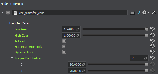
Axles#
Assign the car_axle component to all dummy nodes representing vehicle's axles (e.g. front_axis and rear_axis). You can create as many axles as you need. For each axle, attach nodes representing wheels as children, and specify them in the corresponding fields of the car_axle component.
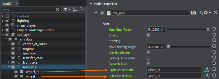
Then specify if the axle is a steering/driving one, if it has a locking differentinal, etc.
Wheels#
Assign the car_wheel component to all nodes representing vehicle's wheels. By adjusting the parameters of this component we can simulate different physical behavior of the vehicle with various types of wheels. Here you can set up wheel mass and radius, friction and additional forces, as well as suspension parameters.

You can enable the Use General Settings option and specify a preset property with general wheel settings for a certain wheel type in the General Settings field to override values of component parameters. This simplifies configuration process: you set all required parameter values for a certain wheel type in a dedicated property, and then use this property for all similar wheels.
Configure Vehicle Body#
As we have all major components configured, let's get them all together. Assign the car component to the object representing the vehicle's body. For this component we should specify necessary car characteristics, such as dimensions, mass, frontal area, etc. along with the number of iterations, which defines joints simulation accuracy. Here we also set up links to dummy nodes with other logic components assigned (engine, gearbox, axles, etc.). Axles are to be specified in the front-to-rear order.

Step 6. Set Up Input Controls#
You can choose to use various types of input devices to control your vehicle, be it a joystick or a gamepad, a driving wheel or a keyboard. The following NodeDummy hierarchy is recommended to implement user input handling:

The car_input_manager component implements vehicle control and enables simultaneous handling of input events from several input devices. It contains an array of nodes (NodeDummy), each having the corresponding input component (car_keyboard_input, car_joystick_input, or car_gamepad_input) assigned. Each component implements input handling for the corresponding device.
Input events can be generated by either of the following:
- a button
- an axis - can be either a physical axis of the controller, or it can be imitated with buttons.
So here we simply configure necessary buttons and axes. Several options are available for an axis:
- Full - full axis range: [-1, 1]
- Positive range - only the positive range of axis values is taken: [0, 1]
- Negative range - only the negative range of axis values is taken: [-1, 0]
- Full to positive - converts values in the full [-1, 1] range to values in the positive [0, 1] range
- Full to negative - converts values in the full [-1, 1] range to values in the negative [-1, 0] range
The NONE value for a button indicates that it's not used.

Debug Configuration (Optional)#
Convincing simulation of any vehicle requires fine-tuning. To simplify the process of adjusting parameters, a set of debug windows displaying various vehicle parameters (engine, transmission, wheels, etc.) is at your disposal.
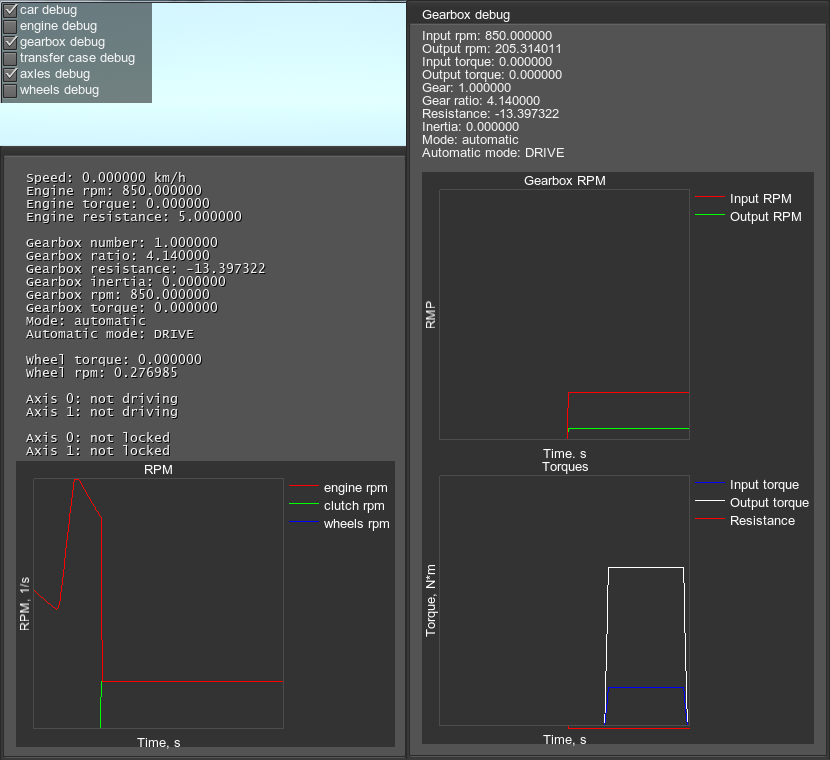
In order to enable the debug option, you should create the following hierarchy of dummy nodes (they're just used to enable component logic) and assign the corresponding components to them as shown below:

Switching Views (Optional)#
You can switch between the driver's view and other custom views (e.g. external cameras, etc.). Suppose you have various cameras (players) added to the scene and placed at desired locations. To enable switching between them, simply add a dummy node to the scene and assign the camera_switcher component to it. Then, in the Input field, specify the node responsible for input handling, that we added at Step 6. And, finally, specify the number of cameras you want to use, and drag the corresponding player-nodes to the fields of the Cameras parameter. All available cameras will be switched in a looped sequence according to the order they are listed.

Road Surface Conditions Simulation#
Driving simulation would be incomplete without the ability to set various surface conditions, such as dry, wet, snow-covered, or icy road, mud, etc. You can simulate various surface conditions by setting up friction coefficients and specifying masks to define areas of the Landscape Terrain for them.
To enable simulation of surface conditions add a dummy node to the scene and assign the friction_controller component to it. Then specify masks of the Landscape Terrain defining the areas to which the values of longitudinal (forward) and lateral friction will be applied.
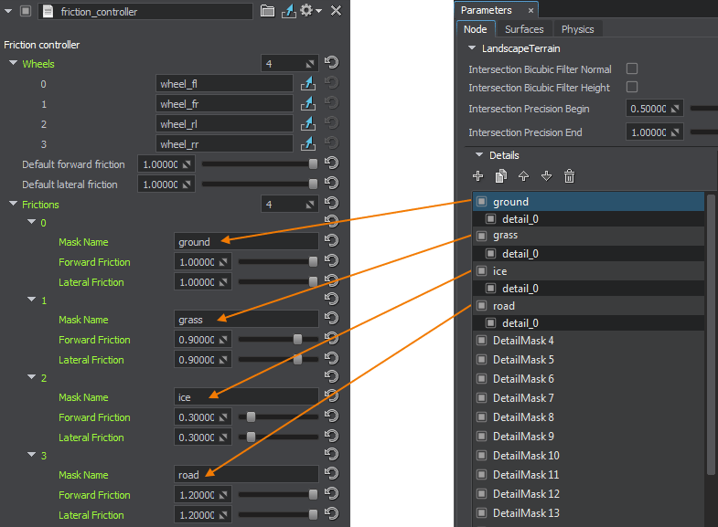
Now you can mark areas with different surface conditions on your terrain and fine-tune your vehicle using the debug windows to make your driving simulation as close to real conditions as possible.