IG Configuration
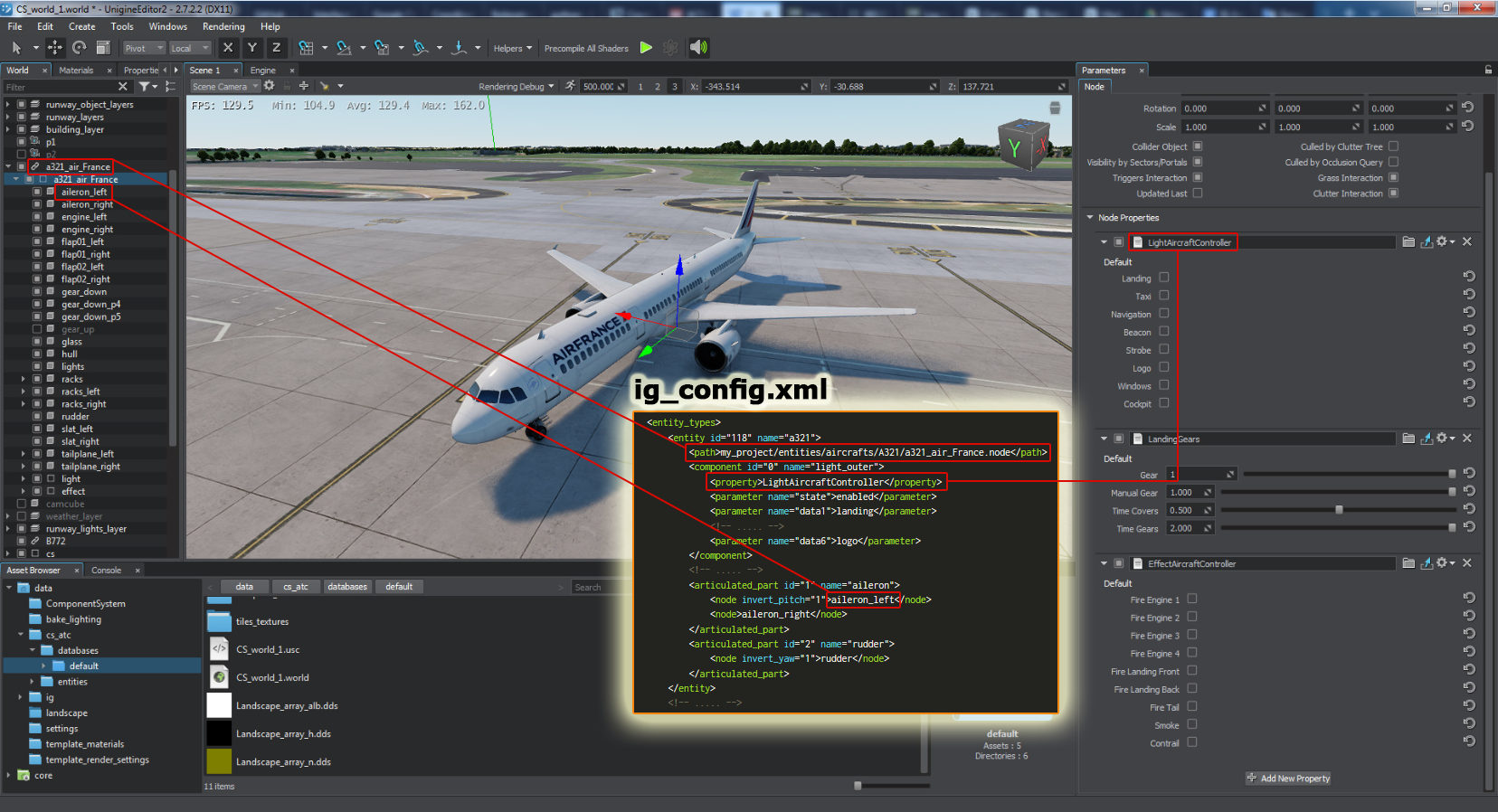
All IG configuration parameters (databases, entity definitions, system settings, connector parameters) are stored in a single file named ig_config.xml. It is an ordinary *.xml file with the following structure (example):
<?xml version="1.0" encoding="utf-8"?>
<ig_config>
<!-- ==== CONNECTOR PARAMETERS ======================= -->
	<cigi_connector>
		<version>3.3</version>
		<host>127.0.0.1</host>
		<send_port>8889</send_port>
		<recv_port>8888</recv_port>
		<view_id>0</view_id>
	</cigi_connector>
<!-- ==== DATABASE LIST ======================= -->
	<databases>
		<database id="1" world_name="world_1"/>
	</databases>
<!-- ==== ENTITY DEFINITIONS ======================= -->
	<entity_types>
		<entity id="118" name="a321">
			<path>my_project/entities/aircrafts/A321/a321_air_France.node</path>
			<component id="0" name="light_outer">
				<property>LightAircraftController</property>
				<parameter name="state">enabled</parameter>
				<parameter name="data1">landing</parameter>
				<!-- ..... -->
				<parameter name="data6">logo</parameter>
			</component>
			<!-- ..... -->
			<articulated_part id="1" name="aileron">
				<node invert_pitch="1">aileron_left</node>
				<node>aileron_right</node>
			</articulated_part>
			<articulated_part id="2" name="rudder">
				<node invert_yaw="1">rudder</node>
			</articulated_part>
		</entity>
		<!-- ..... -->
	</entity_types>
	<!-- ===== SYSTEM SETTINGS ======================= -->
	<systems>
		<meteo>
			<visibility_transition_time>15.0</visibility_transition_time>
			<precipitations_transition_time>5.0</precipitations_transition_time>
			<cloud_transition_time>15.0</cloud_transition_time>
		</meteo>
	</systems>
<!-- =========================================== -->
</ig_config>
Connector Parameters#
Configuration parameters for connectors are enclosed in the corresponding tag, e.g. <cigi_connector/> for CIGI-connector:
<cigi_connector>
	<version>3.3</version>
	<host>127.0.0.1</host>
	<send_port>8889</send_port>
	<recv_port>8888</recv_port>
	<view_id>0</view_id>
</cigi_connector>
The following tags are available:
- version - CIGI protocol version
- host - CIGI Host IP-address
- send_port - TCP port number to be used for sending packets to the CIGI Host
- recv_port - TCP port number to be used for receiving packets from the CIGI Host
- view_id - ID of the view to be used
System Settings#
The list of databases (worlds with terrains) is enclosed in the <databases/> tag. You can specify as many worlds as required.
<systems>
	<meteo>
		<visibility_transition_time>15.0</visibility_transition_time>
		<precipitations_transition_time>5.0</precipitations_transition_time>
		<cloud_transition_time>15.0</cloud_transition_time>
	</meteo>
</systems>
The following tags are available:
- meteo - meteorological conditions (fog, clouds, precipitation)
- visibility_transition_time - time, in seconds, for gradual change of visibility conditions (fog, etc.)
- precipitations_transition_time - time, in seconds, for gradual change of precipitation
- cloud_transition_time - time, in seconds, for gradual change of cloudiness
Databases#
The list of databases (worlds with terrains) is enclosed in the <databases/> tag. You can specify as many worlds as required.
<databases>
	<database id="1" world_name="world_1"/>
	<!-- ..... -->
	<database id="n" world_name="world_n"/>
</databases>
The following attributes are available:
- id - ID of the database (used when loading databases)
- world_name - name of the corresponding *.world file
Entity Definitions#
An IG has a number of models, that are used to represent certain entities in the virtual environment. Entity definition section is enclosed in the <entity_types/> tag. To define each entity the <entity/> tag is used. Each entity includes the following:
- a *.node file containing the hierarchy of nodes representing the entity in the virtual world. A path to this file is specified in the <path/> tag.
- a set of components (flashing lights, aircraft propellers, afterburners, landing gear, tank tracks, wheels, and like items). Definition of each component is enclosed in the <component/> tag. NoticeComponent data in packets, received by IG from connectors, is usually represented as a set of a discrete state and up to six values (data1, data2 ... data6). IG component definitions in this section are actually used to map parameters from connectors to corresponding properties (e.g. data1 field of the outer_light component in the example below corresponds to landing light type).
- a set of articulated parts (ailerons, flaps, etc.). Definition of each articulated part is enclosed in the <articulated_part/> tag.
 Below is an example of entity definition section:
<entity_types>
	<entity id="111" name="b52">
		<path>my_project/entities/aircrafts/B52/b52.node</path>
		<component id="0" name="light_outer">
			<property>LightAircraftController</property>
			<parameter name="state">enabled</parameter>
			<parameter name="data1">landing</parameter>
			<!-- ..... -->
			<parameter name="data6">logo</parameter>
		</component>
		<!-- ..... -->
		<articulated_part id="1" name="aileron">
			<node invert_pitch="1">aileron_left</node>
			<node>aileron_right</node>
		</articulated_part>
		<articulated_part id="2" name="rudder">
			<node invert_yaw="1">rudder</node>
		</articulated_part>
	</entity>
<!-- ..... -->Components#
Each entity may have an arbitrary number of components assigned, including custom ones. To define a component of an entity use the <component/> tag:
<!-- ..... -->
	<entity id="118" name="a321">
		<path>my_project/entities/aircrafts/A321/a321_air_France.node</path>
		<!-- ..... -->
		<component id="22" name="rotorwash">
			<property>rotorwash</property>
			<parameter name="data1">wind_percent</parameter>
			<parameter name="data2">sand_percent</parameter>
		</component>
		<!-- ..... -->
	</entity>
<!-- ..... -->
Components are added to entities by means of assigning corresponding properties to nodes. By default it is assumed that all properties corresponding to components are assigned to the root node. In fact, a component's property can be assigned to any node in entity's hierarchy. For such a component you should add the <node/> tag to specify a path to this node (the path is specified relative to the root node):
<!-- ..... -->
	<entity id="118" name="a321">
		<path>my_project/a321_air_France.node</path>
		<!-- ..... -->
		<component id="22" name="rotorwash">
			<property>rotorwash</property>
			<node>path_to_node</node>
			<parameter name="data1">wind_percent</parameter>
			<parameter name="data2">sand_percent</parameter>
		</component>
		<!-- ..... -->
	</entity>
<!-- ..... -->- <node>path_to_node_reference/^/path_inside_nodereference</node>
Example:
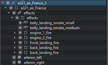
Suppose for a hierarchy shown below we have the comp1 component's property assigned to the aileron_left node, and comp2 component's property assigned to the engine_1_fire node. Definition of components will look like:
|
Source code (XML)
|
Articulated Parts#
Each entity may have an arbitrary number of articulated parts (e.g. flaps, slats, etc.). To define an articulated part of an entity use the <articulated_part/> tag:
<entity_types>
	<entity id="111" name="b52">
		<path>my_project/entities/aircrafts/B52/b52.node</path>
		<!-- ..... -->
		<articulated_part id="1" name="aileron">
			<node invert_pitch="1">aileron_left</node>
			<node>aileron_right</node>
		</articulated_part>
		<articulated_part id="2" name="rudder">
			<node invert_yaw="1">rudder</node>
		</articulated_part>
	</entity>
<!-- ..... -->For each articulated part a corresponding node should be specified using the <node/> tag. Paths are specified relative to the root node, the same way as for components.
- <node>path_to_node_reference/^/path_inside_nodereference</node>
