NormalMapper
NormalMapper is a versatile and fast tool to generate a bunch of height-based textures in one run:
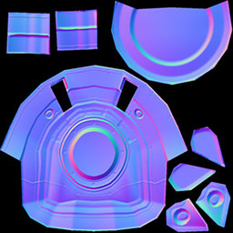
- A high quality normal map.
NoticeTo increase the accuracy and flexibility of generation, control the direction of ray tracing using a cage mesh.
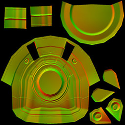
- A parallax map.
- A height map for tessellation.
- An additional surface texture to aid artists in selecting and painting separate surfaces.
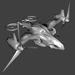
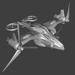
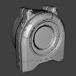
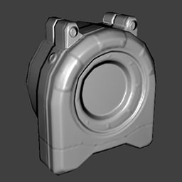
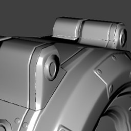
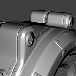
These textures are created for a low-poly model based on a corresponding high-poly model. The resulting maps being applied to the low-poly mesh at rendering time drastically improve its look making it similar to the a high-poly version.
The main advantage over a heightmap-based normal map generator, which usually uses a diffuse texture, is a compensation of distortion of normals. The compensation is done in such a way that the resulting normals, after they are applied, will be the same as for the high-poly model. This can never be achieved with 2D normal map generators.
Usage
To create a normal map along with a parallax map, a height map and/or a surfaces texture, you need to do the following:
- Load a low-poly mesh by clicking Load Low.
- Load a high-poly mesh by clicking Load High.
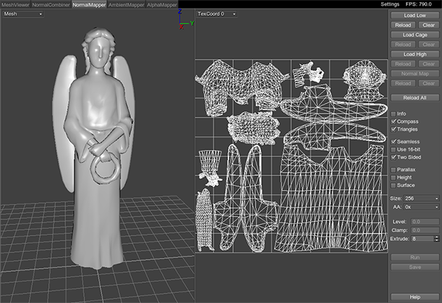
- Set normal mapping options at the right side of the ResourceEditor window.
- If besides a normal map other textures should be generated, specify the Parallax, Height and/or Surface options.
- For baking parallax and height maps for one mesh:
- Set the Level to 0 to bake real maximum height displacement.
- Set the Clamp to 0 not to clamp any heights.
NoticeIf several separate meshes are parts of one object and it is necessary to bake their displacement relative each other, see details here. - Click Run to start generation.
- Switch to the Normal Map mode to check the generated normal map.
- Click Save to save all checked textures.
Display Modes
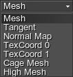
NormalMapper has two viewing panes. The display mode can be switched in the the drop-down list in the upper left corner of each pane:
 |
|
File Options
The set of file options is present at the right side of the window:
| Load Low | Load a low-poly mesh for which a normal map will be baked.
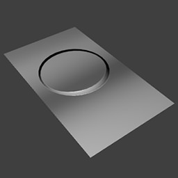
Low-poly mesh
Notice
You can also load the low-poly mesh by pressing Ctrl+O. |
||||||
|---|---|---|---|---|---|---|---|
| Reload | Reload a mesh/normal map. | ||||||
| Clear | Clear a mesh/normal map. | ||||||
| Load High | Load a high-poly mesh basing on which a normal map will be baked.
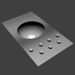
High-poly mesh
Notice
You can also load the high-poly mesh by pressing Ctrl+H. |
||||||
| Load Cage | Load a cage mesh. This mesh that allows cleaner baking of the normal map.
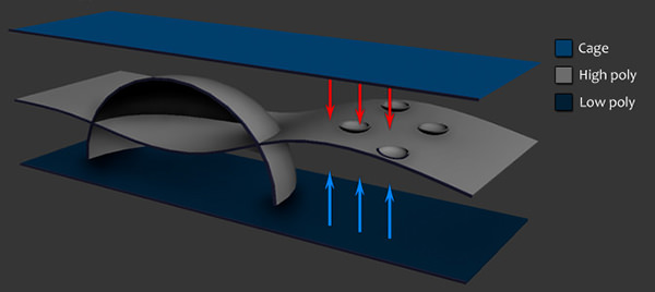
Without a cage, the rays are cast from the low-poly mesh to the high-poly one (in both directions along the normals of a low-poly). It is done to determine what point of a high-poly mesh (full geometry of which allows to calculate per-vertex normals) corresponds to a low-poly mesh point. Whatever point is intersected first, it gets to be baked into the map. However, if there are complex geometry details in the high-poly model or overlapping surfaces, the first met point may not be a proper one. Instead of baking an outer surface, an underneath one that is closest to the low-poly mesh will be baked into a map. A cage allows to avoid such situations. When loaded, the rays are traced from it rather then from a low-poly mesh.
Without a Cage, rays are traced from a Low-poly mesh. With a Cage, rays are traced from it.
Let's take an example as illustrated above (in section): we have a low-poly mesh (a simple plane) and a high-poly mesh, which has details above its surface. We can also load a cage that is above both a low- and a high-poly mesh.
Notice
You can also load the cage mesh by pressing Ctrl+C. |
||||||
| Normal Map | Load an additional normal map. The generated normal map will be combined together with the loaded one. This option allows to create bumping very easily. Additional normal map is displayed in the High mesh mode, i.e. applied to a high-poly model.
Additional normal map
Notice
You can also load the normal map by pressing Ctrl+N. |
||||||
| Reload All | Reload all resources.
Notice
You can also reload resources by pressing Ctrl+R. |
Visualization Options
The set of visualizations options:
| Info | Display information about the mesh that is currently in the viewport. Such data is shown as the number of surfaces, vertices and triangles. After Run was once clicked, the real maximum displacement between a low-poly and a high-poly mesh is displayed.
Notice
You can also enable the option by pressing I. |
|---|---|
| Compass | Toggle an XYZ compass in the upper right corner of the viewport.
Notice
You can also enable the option by pressing C. |
| Triangles | Toggles showing a base grid plane.
Notice
You can also enable the option by pressing T. |
Normal Mapping Options
The set of normal mapping options:
| Seamless | Optimization for UV seams (recommended for tessellation height maps). This option averages the color of corresponding pixels on each side of the seam. Only one-pixel border is affected. | ||||||||||
|---|---|---|---|---|---|---|---|---|---|---|---|
| Use 16-bit | Create a normal map with a 16-bit precision. It be of better quality, but larger in size. If unchecked, a map with 8-bit precision will be created. | ||||||||||
| Two Sided | Use two-sided intersections. | ||||||||||
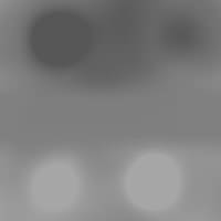
| Parallax | Create a parallax map (with _p postfix in the name). The parallax displacement is calculated basing on the high-poly model.
White color represents no parallax displacement; black represents maximum lowering for pixels (according to the set Level).
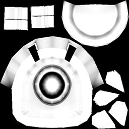
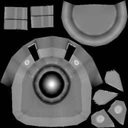
Generated tessellation height map
|
||||||||||
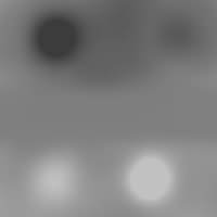
| Height | Create a height map for tessellation (with _h postfix in the name). The height displacement is calculated basing on the high-poly model.
Black color represents no tessellation displacement; white represents maximum elevation for vertices (according to the set Level).
Generated tessellation height map
|
||||||||||
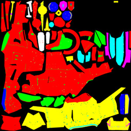
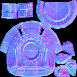
| Surface | Create a texture with randomly colored surfaces (with _s postfix in the name). This texture is not used inside the Unigine engine, it is for artists only. It can be used to conveniently select the contour of a separate surface in 2D graphics editors.
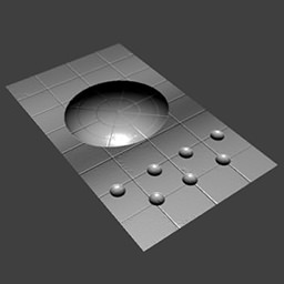
Generated surfaces texture
|
||||||||||
| Size | Size of the generated textures. | ||||||||||
| AA | Anti-aliasing mode for the output normal map. If used, consumes additional memory. The higher the value, the softer and more blurred the normal map will be.
|
||||||||||
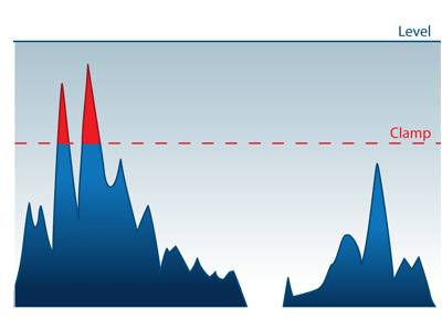
| Level Clamp |
Level and Clamp parameters allow to control how the calculated displacement values are baked into the textures. These options are in effect for both a parallax and a height map.
Level and Clamp
Level. NormalMapper automatically normalizes the displacement range from 0 to 1 (255 gradations for 8-bit texture). What height in units will be equal to the maximum 1, is controlled by the Level parameter. All heights above it are cut out and not baked into the texture.
For example, if a height map should be created basing on this high-poly and low-poly meshes: 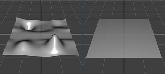
Changing the level will bring the following. Note that the zero level at the middle did not change, only the peaks are baked differently:
Clamp parameter allows to cut off displacement values that are above the specified line within a set Level range. (See illustration above).
How to use Level and Clamp parameters for baking several meshes:
|
||||||||||
| Extrude | Extrusion in pixels for all generated textures. This option adds colored pixels around the contour of each UV shell. The color value is simply copied from the nearby pixel. It allows to get rid of possible darkening where seams meet.
Extrusion
|
||||||||||
| Run | Create textures: a normal map and all the others for which options are checked (parallax map, height map and a surfaces texture). The normal map applied to the low-poly mesh can be seen in the Normal map mode. | ||||||||||
| Save | Save created textures. Specify the name of the normal map with a postfix _n at the end and all other textures (with options checked) will be named accordingly:
Notice
All these textures will be saved into the same format as a normal map. There are several options for saving:
Notice
You can also save the mesh by pressing Ctrl+S. |
Supported File Formats
Supported formats of geometry data:
- Unigine mesh (.mesh)
- Unigine skinned mesh (.smesh)
- Wavefront (.obj)
- COLLADA (.dae)
Supported formats of textures:
- Targa (.tga)
- Portable Network Graphics (.png)
- JPEG (.jpg)
- Photoshop Document (.psd)
- Direct Draw Surface (.dds)
- Portable Pixmap (.ppm)
- Portable Graymap (.pgm)
- High Dynamic Range (.hdr)
- Silicon Graphics Image (.sgi)
Hot Keys
- Ctrl+O — load a low-poly mesh.
- Ctrl+H — load a high-poly mesh.
- Ctrl+C — load a cage mesh.
- Ctrl+N — load an additional normal map.
- Ctrl+R — reload all resources.
- Ctrl+S — save the generated normal map and other textures, if specified.
- I — toggle mesh info.
- C — toggle a XYZ compass.
- T — toggle base grid, surface triangles or a wireframe.
- F1 — show the help window.
