Shadow Mapping

The idea of the shadow mapping consists in testing whether a pixel is visible from the point of view of the light source by matching it with the depth image created for this light. The general rendering algorithm is divided into two stages: the creation of the the shadow map (also called the depth map) and actual rendering of the scene using this map.
Shadow Map Creation
On the first stage, the scene is rendered from the point of view of the light source. For the omni (point) light, a perspective projection is used, and for the directional light (like the Sun), an orthographic projection is used. It is usual to disable updating of the color buffers and lighting/texture calculations to save rendering time, as only the depth values are actually important.
Then, the z-buffer values are extracted from this rendering. They are saved as a texture (a depth map) in a graphics memory. For the omni light, the map is saved in a cube texture, which usually requires six drawings, but graphics cards that support Direct3D 10 can do it in one pass. For the directional light, an ordinary 2D texture is saved, which requires only one drawing. This map needn't be updated when the viewer moves, but if the light source or some object position is changed, it should be recalculated.
Adding Shadows to the Scene
After a depth map is created, it should be applied to the target scene. This is done in three steps:
- Point coordinates in the target scene are transformed to the coordinates used for rendering of the shadow map. This transformation can be applied on the vertex level. In this case, to find values between vertices, interpolation is used.
- Once the coordinates are found, we can now test the transformed z-value of the point against the depth map. If it is greater than the corresponding value in the map, the point is considered to be behind an obstruction, the test is failed, and the point will be rendered in shadow. Otherwise, it will be drawn lit.
- The final scene is rendered depending on the results obtained from the depth map test.
Advantages and Disadvantages
Shadow mapping is a very popular technique due to its numerous advantages:
- It is fast on complex scenes.
- For directional light, only one texture can be used.
-
Transparency and self-shadowing can be fully used.
 Translucent objects and their shadows are rendered correctly
- No geometry limitations (the light occluder need not form a closed geometry).
Difficulties are also present, and they are mainly related to dimension restrictions of the shadow maps. The shadow maps are effectively textures, and the maximum size of a texture is limited by the graphics memory capabilities.
- Limited accuracy due to texture size limits. This can be overcome by dividing a large scene into several regions. For that purpose such technique as PSSM can be used.
-
Aliasing also occurs because of the representation as a texture. The remedy consists again in splitting into parts (see above) or using such method as PSSM. It allocates more texture space for the near visible objects and less space for the far objects.
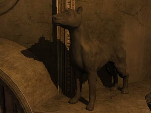
 Note unevenness of shadow edges in this image caused by small texture size
- Shadows cannot be rendered soft by default. Additional filtering is needed.
Other Notes
In Unigine shadow mapping is implemented in hardware. As opposed to the software shadow mapping that uses an ordinary texture for depth map creation, hardware one uses a dedicated texture and a set of special operations for it.
In software shadow mapping, when the final scene with shadows is rendered, the renderer reads values from the shadow map (which is effectively a color texture), as described above. However, the renderer also needs a depth map for the current position of the viewer to correctly apply shadows.
In hardware shadow mapping, the scene is rendered directly into a special depth texture that does not require any additional textures/maps to draw shadows. This allows performing hardware shadow mapping way faster, but yields two problems.
- Not all graphics cards can render cube depth textures for omni lights, and these textures are emulated as a set of 2D textures. Such emulation can produce artifacts, which can be avoided by elaborating more complex shaders, and at some point the hardware implementation of shadow mapping loses its speed advantage relative to the software implementation. Only the cards that support Direct3D 10 create genuine cube depth textures.
- Different vendors provide different implementations. For example, if you want to use a filter that renders soft shadows, the final result will not be the same for ATI and NVIDIA cards — NVIDIA shadows will be softer. In such cases you need to use software shadow mapping instead.