Projections with AppProjection Plugin
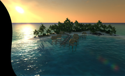
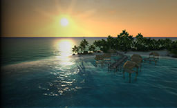
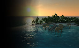
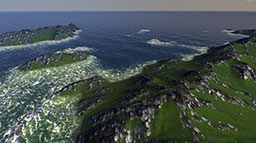
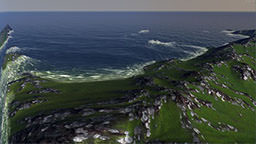
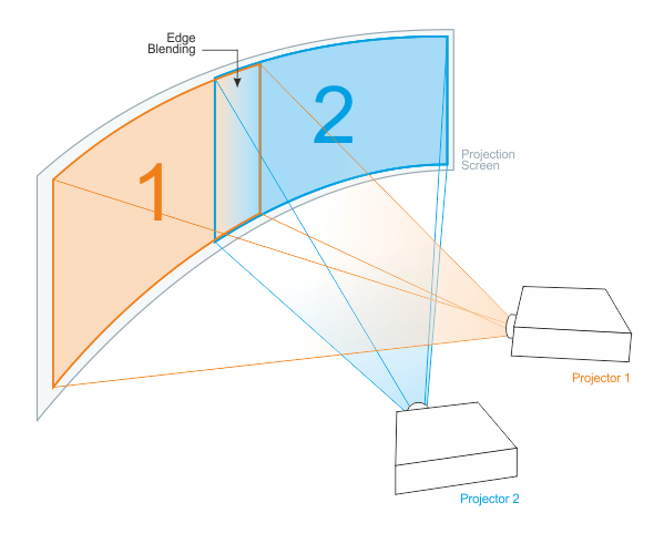
AppProjection allows to create multi-projector setups. Edge blending, non-linear image mapping and color correction for each projection are supported. Due to that, AppProjection can project images onto large curved screen displays covering 360 degrees, if necessary. Moreover, each projection can be fully customized to use required view frustums.
See Also
- engine.projection functions
Launching AppProjection
To launch the application and render projections:
- Specify an engine plugin library (lib/AppProjection_*) together with the rest of required start-up arguments (such as rendering API, window size, etc.). For example:
Shell commandsYou can use 32-bit, 64-bit, debug or release versions of the library. (The engine automatically loads the appropriate version of the library depending on the specified main application.)
bin\main_x86d.exe -extern_plugin AppProjection
NoticeIt is not possible to use AppProjection with other App* plugins:- Multi-monitor ones (AppWall, AppSurround)
- AppPanorama
- Stereo 3D
- To change the number of displays in a row, specify -width CLI option. For example:
Shell commandsBy default, up to 5 projections are supported to be output from one rendering node.
bin\main_x86d.exe -extern_plugin AppProjection -width 2
Setting Up Projections
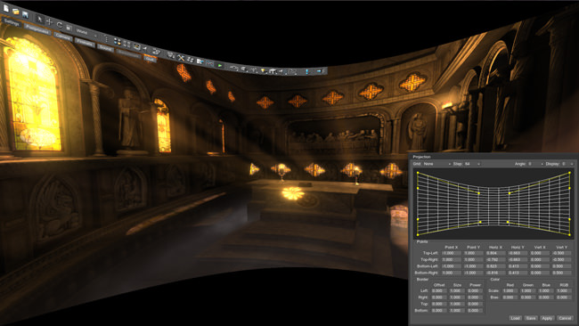
To set up projections, open the main menu by pressing Esc, go to Wall tab and click Projection button. Here, it is possible to:
- Rotate displays
- Control curvature for each display
- Set up edge blending for each projection
- Correct color intensity
For the last three options, choose a display to be corrected first.

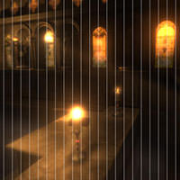
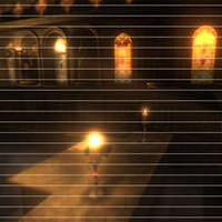
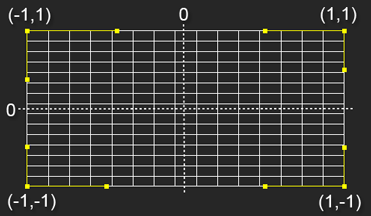
| Grid | Renders a grid over displays to facilitate setting up its curvature. It has the following modes:
|
||||
|---|---|---|---|---|---|
| Step | Changes the grid step for finer adjustment.
|
||||
| Angle | Rotates all projections by:
|
||||
| Display | Allows for choosing one display in the drop-down list to set up its curvature, edge blending and color correction options. | ||||
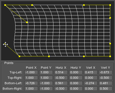
| Points | It is possible to set up projection curvature in the visual editor or by specifying numerical values in Points.
|
||||
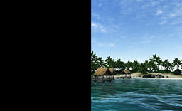
| Border | Controls soft edge blending for each side of the projection (left, right, top or bottom one). Set non-zero Power to start setting it up.
|
||||
| Color | Allows you to correct the color intensity, as well as adjust the color balance.
|
||||
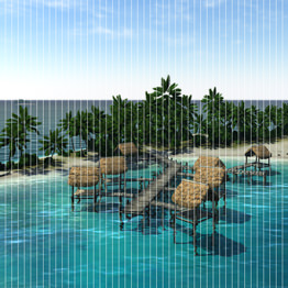
| Linearity | Controls non-linear stretching for each side of the projection (left, right, top or bottom one).
|
Multiple Projections' Viewing Settings
If more than two projections are created with AppProjection, the following viewing settings can be tweaked in the Main menu -> Wall.
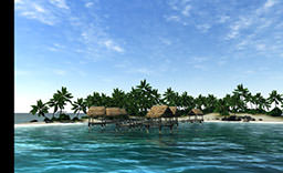
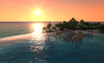
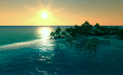
| FOV | The field of view for all projections. (Tools panel -> Camera tab -> Field of view option is not applicable in this case).

Fov = 60

Fov = 80
|
|---|---|
| Angle | Allows to adjust the viewing angle between projections. That is, when surfaces to project the images onto are turned at some angle to each other, this angle can be entered as Angle value and the projection will be automatically recalculated to show the right image.
For example, if two surfaces are turned to each other at 40 degrees:

Angle = 40 degrees
|
| Bezel X | Compensates for horizontal bezel of monitors. Positive values decrease the viewport space; negative ones increase it (for overlapping). |
Saving and Loading Presets
After projection configuration is set up, it can be saved into an XML preset file (*.projection) to be loaded at any time:
- Save button to save a preset file
- Load button to load a preset file
Customizing AppProjection
AppProjection can be customized to support custom viewing frustums (symmetric or asymmetric ones) for each projection.
AppProjection Viewports
AppProjection have one primary viewport, while all others are rendered as auxiliary ones. By default, the primary display is the Unigine engine viewport used for one-monitor configuration. It uses matrices of the Player used by the engine to view the scene. Other displays are arbitrary cameras with any perspective and facing whatever direction needed. Each display has its own model-view and projection matrices. Both the primary projection and auxiliary ones can be enabled or disabled, if necessary.
- The primary viewport can be set to any projection (for supported configurations it is already set).
- Each viewport has its own model-view and projection matrices.
- By default, only a primary one has an interface (render system GUI, editor widgets, wireframe, or the profiler). However, separate GUIs can be drawn on all projections.
- All viewports have their own viewport and reflection mask to selectively render nodes and reflections from them.
Default Configurations
For default configurations, the primary viewport is set to the following projection:
- For 2 projections, the 1st viewport.
- For 3 projections, the 2nd viewport.
- For 4 projections, the 2nd viewport.
- For 5 projections, the 3rd viewport.
How to Customize Projections
Rendering of AppProjection viewports is controlled by wall.h script (found in <UnigineSDK>/data/core/scripts/system/ folder). There are two possible setups depending on how the primary projection is rendered. It can be drawn by:
- The default engine renderer (the same as when a usual one-monitor application is rendered).
- The AppProjection renderer itself (which is safer if you are going to use asymmetric frustum for the center projection and modify its model-view matrix).
The following example demonstrates how to tweak cameras configuration and choose the renderer for the main projection.
1. Using default engine renderer
The first variant is to render the main (primary) projection by the default engine renderer.
- In case the created configuration is not already supported, set the primary projection via engine.projection.setPrimary():
Source code (UnigineScript)
	// Set the first projection as a primary one
	engine.projection.setPrimary(0,1);
- Enable all non-primary projections via engine.projection.setEnabled(). The main one should be left disabled, as it is drawn by the default engine renderer.
Source code (UnigineScript)
	// Enable the 2nd projection in a row
	// The second argument of the function sets 'enabled' flag
	engine.projection.setEnabled(1,1);
- Set projection and model-view matrices for an auxiliary projection via engine.projection.setProjection() and engine.projection.setModelview().
Source code (UnigineScript)
	// Settings for the 2nd projection
	engine.projection.setProjection(1,projection_1);
	engine.projection.setModelview(1,modelview_1);
2. Using AppProjection renderer
Another variant is to render the main projection by the AppProjection renderer. This variant can be used, for example, if you want to set up symmetric frustums for all projections.
- Set the projection to be used as a primary one and enable its rendering by AppProjection.
Source code (UnigineScript)
	// Set the first projection as a primary one
	// The second argument of the function sets 'enabled' flag
	engine.projection.setPrimary(0,1);
- Disable rendering into the default Unigine viewport via engine.render.setEnabled():
Source code (UnigineScript)
engine.render.setEnabled(0);
- Enable all AppProjection projections including the primary one. As a result, all viewports will be rendered by AppProjection renderer itself:
Source code (UnigineScript)
	// Enable all projections
	engine.projection.setEnabled(0,1);
	engine.projection.setEnabled(1,1);
- Set model-view and projection matrices for all projections.
Source code (UnigineScript)
	// Settings for the 1st projection
	engine.projection.setProjection(0,projection_0);
	engine.projection.setModelview(0,modelview_0);

	// Settings for the 2nd projection
	engine.projection.setProjection(1,projection_1);
	engine.projection.setModelview(1,modelview_1);

