Rope Body
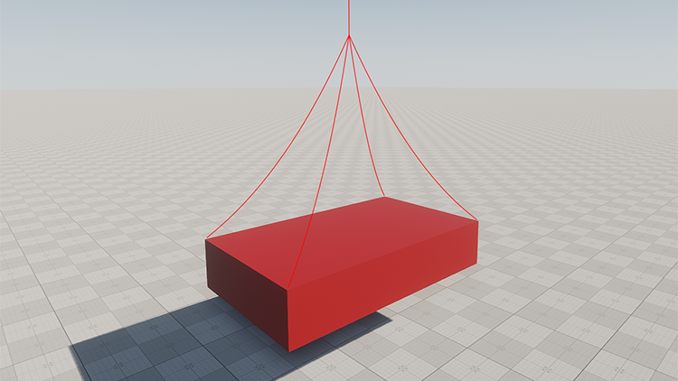
Rope body enables physical simulation of ropes, cables, wires, etc. This body uses the Mass-Spring model for simulation, ensuring the rope ability to fold, stretch and even tear.
Rope enhances the realism of simulated environment and saves the time of game artists as it replaces animation. However, simulation of this type of body is quite costly and it is strongly recommended to use distance optimization to avoid performance hits.


Ropes can be pinned to a Rigid, RagDoll or Dummy body.
To pin a rope to a body so it would hang freely, or tie several bodies, the Particles joint should be used.
See also#
- BodyRope class
- BodyParticles class
- Example illustrating the use of Rope body and Particles joint
- Fragment of the video tutorial on physics illustrating simulation of wires and ropes using Rope body
Mesh Requirements#
The only acceptable mesh type for a Rope body is a cylinder. You can use a standard primitive cylinder to create a rope. The workflow in this case is as follows:
- On the Menu bar, click Create -> Primitive -> Cylinder.
-
Specify desired rope parameters (length, radius) for a cylinder, e.g. the following:

- Click OK and place the cylinder somewhere in the world. It is created as a Static Mesh object. The object itself can be deleted, its mesh however is still available in the data/ folder.
- Create a Dynamic Mesh object and use the cylinder mesh for it.
- Assign the Rope body to the created dynamic mesh object.
Assigning a Rope Body#
To assign a Rope body to an object via UnigineEditor perform the following steps:
- Open the World Hierarchy window.
-
Select a dynamic mesh object to assign a Rope body to.
NoticeMake sure that the object's mesh meets requirements! -
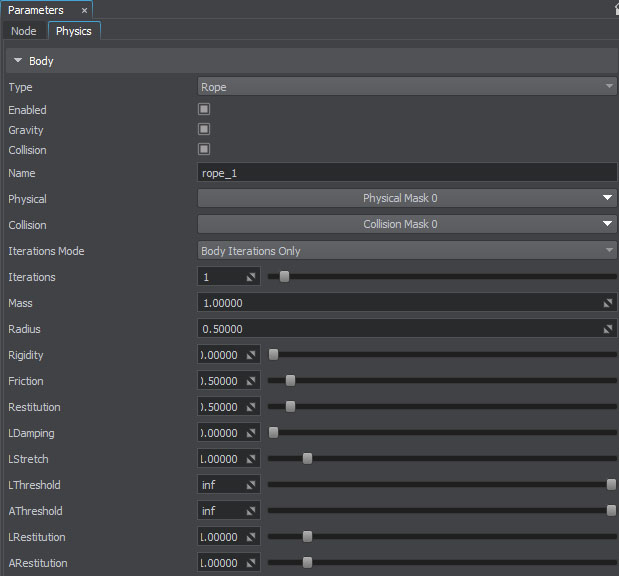
Go to the Physics tab in the Parameters window and assign a physical body to the selected object by selecting Body -> Rope.

- Set the body's name and change other parameters, if necessary.
Attaching a Rope#

Ropes can be attached to the following types of bodies:
To attach a rope to a body, use the Particles joint. In case of Rigid body (either static or dynamic) and Dummy body, pinned particles stay fixed in their position and follow transformations of attached objects pulling the rope with it.
- Select Rigid body, RagDoll body or Dummy body.
- Add Particles joint.
- Specify Rope body.
- Adjust the pinning area using the Threshold and Size parameters of the Particles joint.
Attachment to Skinned Mesh#
Convincing simulation of the rope on a Mesh Skinned character requires a different approach. To follow bones transformations, each vertex of the rope that is found in the Particles joint area is mapped to the nearest Mesh Skinned vertex (up to the distance specified by the Threshold parameter of the particles joint).
For example, we need to create a rope that is glued to the hand of a Mesh Skinned character while the rest of the rope hangs and moves loosely. It is done in the following steps:
- When creating a Mesh Skinned, add a rope segment surface identical to the clipped part that needs to be pinned. In our case, it's the rope part in a hand.
- Add Mesh Skinned that has a RagDoll body assigned. Make sure that the rope segment surface is enabled.
- Add a separate dynamic rope mesh and synchronize its position with Mesh Skinned character. Turn off physical simulation (CTRL + SPACE) and assign a Rope body.
- Attach Rope body to RagDoll body. If the Threshold distance of the particles joint is set low enough, the physical rope will be automatically attached only to the rope segment surface (i.e. hand). After that, the rope segment surface is simply disabled and does not provide any load at all.
Parameters#
| Gravity | Toggles the gravity for the body on and off. |
|---|---|
| Collision | Toggles collision detection for the rope body on and off. |
| Name |
Name of the body. This name may become helpful for identification when creating joints, detecting contacts, handling callbacks, etc. |
| Iterations Mode |
The mode that determines how the number of iterations for solving the constraints of the particles body is calculated. By selecting the suitable mode for each rope body you'll have flexibility in fine-tuning of performance and simulation quality.
|
| Iterations |
The number of iterations controls the accuracy of the solution of rope inner joints. This number indicates how many times the joints are solved per physics frame. Joints are solved in a random order to provide more predictable stretching results.
Increasing the number of iterations may help to avoid twitching of a rope. |
| Mass |
Mass of the body, in kilograms. Notice
Do not use real masses, this can make physics simulation unstable. Adjust mass values when necessary to achieve realistic behavior (e.g. for a wheel mass of 25 kg it might be better to set 60 kg for a car body instead of 2000 kg). It is very important to ensure mass balance – avoid connection of too heavy bodies to very light ones, otherwise the joints may become unstable! |
| Radius |
Radius of the particles forming the rope body and represented as sphere shapes. Rope particles use continuous collision detection, so higher values are preferable for more robust behavior. Collisions between the particles are not calculated and should not be considered when setting a radius. Be careful, however, as particles too big in diameter can provide incorrect interaction with environment (twitching or blowing up of the rope). Too low radius results in poor collision handling. |
| Rigidity |
Additional constraint of the rope motion to control its stiffness and flexibility:
|
| Friction |
Friction coefficient of the body, enables modeling of rough rubbing of surfaces. The higher the value, the less tendency the body has to slide. |
| Restitution |
Coefficient of restitution determines the degree of relative kinetic energy retained after a collision. It defines how bouncy the object is when colliding with another object:
|
| LDamping |
Linear damping reduces linear velocity of the body over time and slows it down up to a complete stop. Higher values make the body slow down faster. Global linear damping is added to the linear damping of the body to calculate resulting value. |
| LStretch | Linear stretch determines the scale for the length of linear joints (relative to the source mesh topology). |
| LThreshold |
Linear threshold sets the distance limit for stretching the rope. When two particles move away from each other further than this limit, joints that connect them break and a the tear appears. Notice
If set to infinity (inf), the rope is stretched without tearing. This value is set by default. |
| AThreshold |
Angular threshold represents a maximum angle to fold the rope relative to its initial state.
|
| LRestitution |
Linear restitution determines how far the rope particles can be stretched apart from each other. It enforces rope joints to restore the distance that was between the vertices of the original mesh:
Notice
0 and near zero values are not allowed because they cause unstable simulation and blowing up of the rope. |
| ARestitution |
Angular restitution determines the possible angle between rope triangles formed by particles. It constrains folding of the rope by enforcing joints to keep the angle that was between the triangles of the original mesh:
Setting up the maximum value (1.0) may provide unsteady behavior. |
Mass-Spring Simulation Model#
The Rope body is modeled as set of point masses (particles) located in the mesh vertices. Each particle is represented with a sphere shape and linked to other particles by inner spring joints that are located along the mesh edges. Inner joints allow recreating the mesh topology as well as restricting stretching and folding.

Each particle is characterized by a position, mass and velocity and has a constant spherical shape with a set radius. The total mass of the whole body is equally distributed among them. In accordance with Newton's second law particles can be acted upon by a force or an impulse applied by inner joints and external forces (collision, gravity, air resistance, wind, etc.).
Self-collision of the particles and collisions between different rope bodies are not calculated. However, the rope interacts with environment by colliding with other physical bodies if the Collision box is checked. Its behavior in case of contact is controlled by such parameters as friction and restitution. Selective physical interaction is available via corresponding bitmasks.
Thus, Rope body can be regarded as a constrained system of rigid particles and therefore shares with Rigid body such parameters as mass, friction, restitution, linear and angular damping.
Due to the fact that particles are represented by spheres, continuous collision detection is used for collisions with other objects. The rope never lies flat on the ground or tightly adheres to the surfaces. There is always a gap equal to particle radius.
Stretching and Folding#
A rope may be deformed by stretching and folding. These deformations are controlled with joint constraints of two types:
- Linear restitution controls stretching.
- Angular restitution controls folding.
With these types of constraints, it is possible to obtain the desired look and feel of the rope and simulate a variety of different deformable materials ranging from a stiff metal wire to an elastic rubber cord.
If the rope is too stretchy and rubbery, try one of the following:
- Set linear restitution to 1.
- Increase the number of joints solver iterations.
- Use the mesh with fewer vertices.
Tearing#
When the rope is stretched or folded beyond its elastic limit, it tears and shreds into pieces. Tearing is caused by applying the force or collision with a physical body, and depends on the rope stiffness (controlled by linear and angular restitution parameters). The rope is torn only along the edges of rope triangles, splitting mesh vertices and duplicating particles.
Optimizing Simulation#
Updating each frame a huge number of objects located far away from the camera that are hardly distinguishable or observed as a mass is a waste of resources.
To improve performance and avoid the excessive load, simulation of the rope can be updated with a reduced framerate. When the player is out of the area specified by the Update Distance Limit, the rope stops to be updated and freezes statically.
The set of frame rates given below enables you to specify how often the rope simulation should be updated when the object is visible, when only its shadow is visible, or when it is not visible at all.
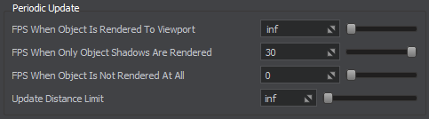
This feature is enabled with default settings ensuring optimum performance and can be adjusted per-object in the UnigineEditor or via API at run time.
The information on this page is valid for UNIGINE 2.20 SDK.