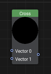
Cross Node
Description
This node computes the cross product of two float3 vectors A and B, resulting in a vector that is perpendicular to both and serves as the normal to the plane they define.
This operation is fundamental in 3D graphics and physics calculations. Use it to:
- Generate normal vectors
- Calculate surface normals
- Find the area of a triangle
- Handle rotational effects in simulations
- Determine the orientation of objects in 3D space, such as aligning a camera or defining the axis of rotation.
Functionality
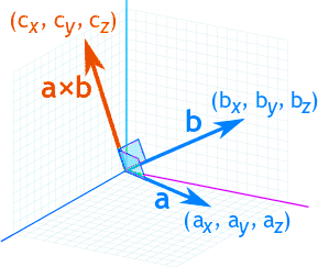
The Cross node takes two vectors as input and calculates their cross product using the formula:
Where:
- A and B are the input vectors.
- The result is a vector perpendicular to both A and B, following the right-hand rule.
- The order of input vectors matters: A x B and B x A return different results.
To Avoid Unexpected Results:
- Ensure input vectors are not parallel, as this would result in a zero vector.
- Normalize input vectors to ensure consistent output scaling.
- Remember that the physical position of the object does not change (i.e. its bound is stable) - only the material behavior creates the visual illusion of rotation.
Usage Examples
Creating A Material Always Facing The Camera
To make an object always face the camera, we need to construct a local coordinate system based on the camera's position relative to the object.
-
Compute the Unit Vector from the object to the camera:
- Use the Camera Position node and normalize the vector to maintain consistent scaling.
-
Determine the Side Vector:
- Use the Cross Node to calculate a perpendicular vector by crossing the unit vector (computed in Step 1) with a fixed up vector.
- Normalize the result vector.
-
Compute the Final Orientation:
- Perform another cross product between the computed side vector (computed in Step 2) and the unit vector (computed in Step 1) to get the final perpendicular vector.
- Use the three orthogonal vectors to construct a transformation matrix that aligns the object to face the camera.
By using the Cross node in this way, we ensure the object dynamically orients itself toward the camera regardless of its movement, making it ideal for billboards, particles, and UI elements in 3D environments.
The information on this page is valid for UNIGINE 2.20 SDK.