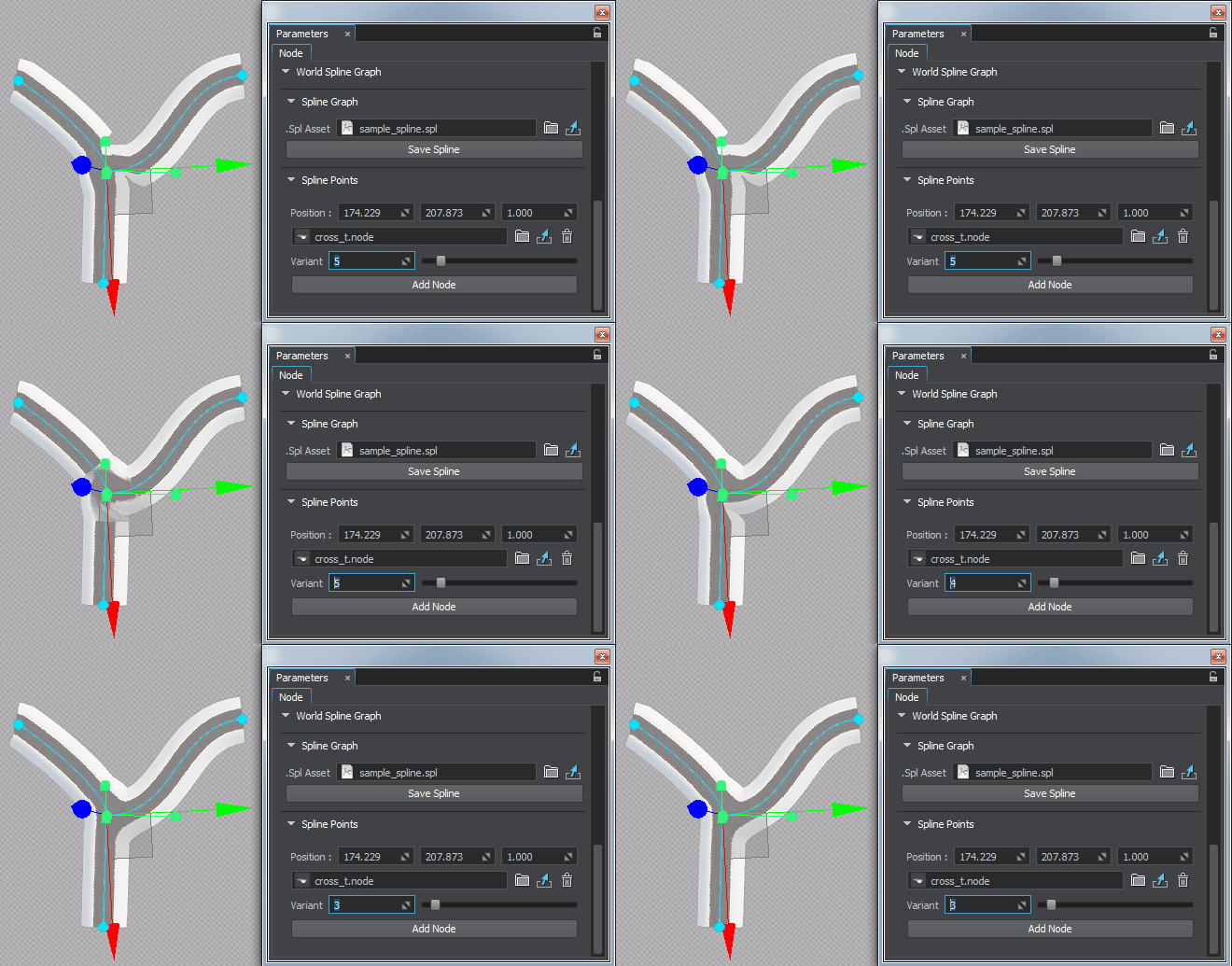
世界样条图

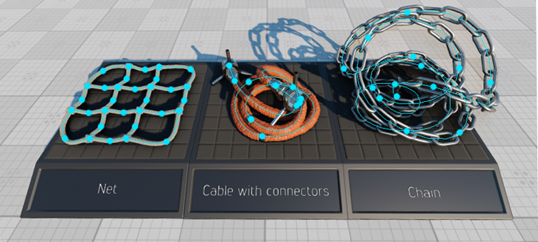
World spline graph is a convenient and performance-friendly method to place specified nodes (called source nodes) along a spline graph (its vertices and edges). It is not a single-purpose tool designed just to create roads. It can also be used for ropes, chains, pipes, and any objects, having a form that follows a curved path. It is designed to help artists quickly build various complex structures from typical basic elements placed along spatial curves, such as pipes and tubes at an oil refinery, for example. 世界样条图是一种方便且性能友好的方法,用于沿样条图(其顶点和边)放置指定的节点(称为源节点)。 这不是旨在创建道路的单一目的对象。它也可以用于绳索,链条,管道和任何物体,它们的形状遵循弯曲的路径。它旨在帮助艺术家根据沿空间曲线放置的典型基本元素(例如炼油厂的管道)快速构建各种复杂的结构。
A spline graph is determined by a set of points p0, p1, ... pn and a set of edges or segments (cubic Bezier splines), that connect some or all of these points.样条图由一组点p0, p1, ... pn和一组连接某些或所有这些点的边或线段(三次贝塞尔曲线样条)确定。
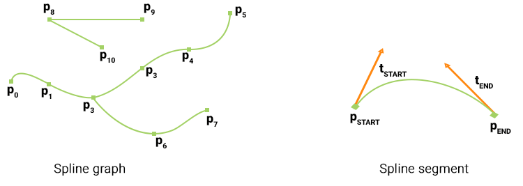
Each segment is determined by a starting (pSTART) and an ending (pEND) point, as well as tangent vector coordinates at these points, which determine the curvature of the segment (tSTART and tEND respectively). Points, that are shared by more than two segments are called junctions.每个分段都由起点(pSTART)和终点(pEND)以及这些点处的切线矢量坐标确定,这些点确定分段的曲率(分别为tSTART和tEND)。由两个以上段共享的 点称为交界处。
Source nodes (currently Static Mesh, Skinned Mesh, and Projected Decal) can be placed at points and along the segments of the spline graph. Each point and segment can have a single or a set of source nodes assigned. One of the following modes can be selected for each individual source node assigned to a segment:源节点(当前为Static Mesh, Skinned Mesh和Projected Decal)可以放置在样条图的点处或沿着样条图的线段放置。每个点和线段可以分配一个或一组源节点。可以为分配给段的每个单独的源节点选择以下模式之一:
- stretching - source nodes are stretched along the spline segment.注意Stretching is available only for Static Mesh source nodes.stretching-源节点沿样条线段拉伸。Stretching is available only for Static Mesh source nodes.Stretching is available only for Static Mesh source nodes.注意Stretching is available only for Static Mesh source nodes.拉伸仅适用于静态网格源节点。
- tiling - source nodes are duplicated along the spline segment.tiling-源节点沿样条线段重复。
- adaptive (a combination of the first two) - source nodes are duplicated along the spline segment, but the length of each node (stretching) is determined by the curvature of the corresponding part of the segment. Thus, long nodes are placed along the straight parts of segments, while short ones - along the curved parts, providing a reasonable balance between the plausible look and performance.adaptive(前两个的组合)-沿样条线段复制源节点,但是每个节点的长度(拉伸)由段的相应部分的曲率确定。因此,长节沿线段的笔直部分放置,而短节沿弯线部分放置,在合理的外观和性能之间提供合理的平衡。
For example, a segment can have two source nodes assigned: one representing the road (stretched) and another for roadway lights (tiled with a gap). 例如,一个路段可以分配两个源节点:一个代表道路(拉伸),另一个代表道路灯(与道路平铺)。差距)。
An arbitrary number of WorldSplineGraph nodes can be added to the scene as it uses a number of optimizations (such as baking elements into large segments etc.) to ensure acceptable performance for large areas.可以将任意数量的WorldSplineGraph节点添加到场景中,因为它使用了许多优化(例如将烘焙元素分成大段等)来确保大面积的可接受性能。
Coordinates of the UP vector are additionally stored for each point of the segment. This vector is used to define orientation of nodes placed along the segments of the spline graph. By default this vector is parallel to the Z axis. The UP vector does not affect the curvature of the spline segment itself.UP矢量的坐标还针对该段的每个点存储。该向量用于定义沿着样条图的线段放置的节点的方向。默认情况下,此向量平行于Z轴。 UP向量不会影响样条曲线段本身的曲率。

SDK includes the Road Tool Constructor add-on with a set of ready-to-use assets (road segments and various types of junctions) that can be used as construction elements to simplify roads creation. SDK包含Road Tool Constructor附加组件,其中包含一组可立即使用的资源(路段和各种类型的交叉路口),可以用作构造元素来简化道路的创建。
- it cannot be converted to a Node Reference.it cannot be converted to a Node Reference.
- it is not supported by Node Layers.it is not supported by Node Layers.
- it cannot be converted to a Node Reference.它不能转换为Node Reference。
- it is not supported by Node Layers.Node Layers不支持它。
See also也可以看看#
- The WorldSplineGraph class article to learn how to manage world spline graphs via APIWorldSplineGraph类文章,学习如何通过API管理世界样条图
- The SplinePoint class article to learn how to manage spline graph points via APISplinePoint类别文章,了解如何通过API管理样条图点
- The SplineSegment class article to learn how to manage spline graph segments via APISplineSegment类别文章,了解如何通过API管理样条图段
- C++ sample for the WorldSplineGraph class illustrating how to manage spline graphs and generate geometry along the graph segments: source/samples/Api/Nodes/WorldSplineGraphWorldSplineGraph类的C ++示例,说明如何管理样条图以及沿图段生成几何: Source / samples / Api / Nodes / WorldSplineGraph
- Samples illustrating use cases of the WorldSplineGraph node included in the Samples suite:
- world_spline_graph/roads - roads created on the terrain surfaceworld_spline_graph/roads - roads created on the terrain surface
- world_spline_graph/ropes - ropes, chains, and cablesworld_spline_graph/ropes - ropes, chains, and cables
- world_spline_graph/roads - roads created on the terrain surfaceworld_spline_graph/roads-在地形表面上创建的道路
- world_spline_graph/ropes - ropes, chains, and cablesworld_spline_graph/ropes-绳索,链条和电缆
Creating a World Spline Graph创建世界样条图#
To create a new World Spline Graph, do the following:要创建一个新的World Spline Graph,请执行以下操作:
- Add a World Spline Graph node: on the Menu Bar, choose Create -> Spline Graph.
添加一个World Spline Graph节点:在菜单栏, 选择Create -> Spline Graph。

- Specify a name of existing spline file (*.spl) to be used for the new World Spline Graph or a new name to create your spline from scratch.
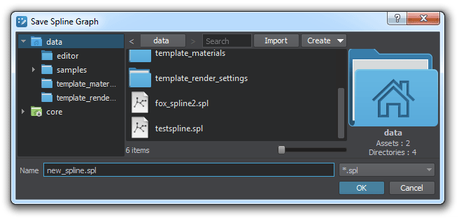 注意Remember, *.world files store only WorldSplineGraph node's data (transformation, list of source nodes, etc.), while spline graphs themselves are stored in separate *.spl files. To save the spline graph that you created in the world, click Save Spline in the Parameters tab and specify a file name for it. 指定要用于新样条文件的现有样条文件(*.spl)的名称World Spline Graph或使用新名称从头开始创建样条线。Remember, *.world files store only WorldSplineGraph node's data (transformation, list of source nodes, etc.), while spline graphs themselves are stored in separate *.spl files. To save the spline graph that you created in the world, click Save Spline in the Parameters tab and specify a file name for it. Remember, *.world files store only WorldSplineGraph node's data (transformation, list of source nodes, etc.), while spline graphs themselves are stored in separate *.spl files. To save the spline graph that you created in the world, click Save Spline in the Parameters tab and specify a file name for it.
 注意Remember, *.world files store only WorldSplineGraph node's data (transformation, list of source nodes, etc.), while spline graphs themselves are stored in separate *.spl files. To save the spline graph that you created in the world, click Save Spline in the Parameters tab and specify a file name for it. 请记住,*.world文件仅存储WorldSplineGraph节点的数据(转换,源节点列表等),而样条图本身存储在单独的*.spl文件中。要保存在世界上创建的样条图,请在Parameters选项卡中单击Save Spline并为其指定文件名。
 - Edit the spline graph by managing its points and segments.通过管理样条图来编辑样条图点数和段。
- Assign desired source nodes to points and segments of the spline graph.分配样条图的点和线段的所需源节点。
Managing Points管理要点#
Adding a New Point添加新点#
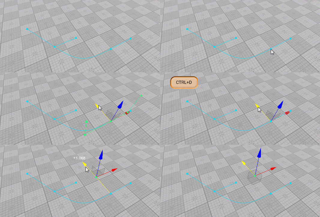
New points are added to the spline graph by cloninng existing ones. To add a new point do the following:通过克隆现有点将新点添加到样条图中。要添加新点,请执行以下操作:
- Select the World Spline Graph.选择World Spline Graph。
- Select the desired point, which you wish to clone (Move manipulator will appear).选择要克隆的所需点(将出现“移动操纵器”)。
- Press Ctrl + D on the keyboard (a new point will be created).在键盘上按Ctrl + D(将创建一个新点)。
- Use the Move manipulator to position you new created point.使用“移动”操纵器来放置新创建的点。
Adjusting Point's Position调整点的位置#
To adjust position of a point do the following:要调整点的位置,请执行以下操作:
- Select the World Spline Graph.选择World Spline Graph。
- Select the desired point (Move manipulator will appear).选择所需的点(将出现“移动操纵器”)。
- Use the Move manipulator as you would do to move a node.使用移动操纵器,就像移动节点一样。
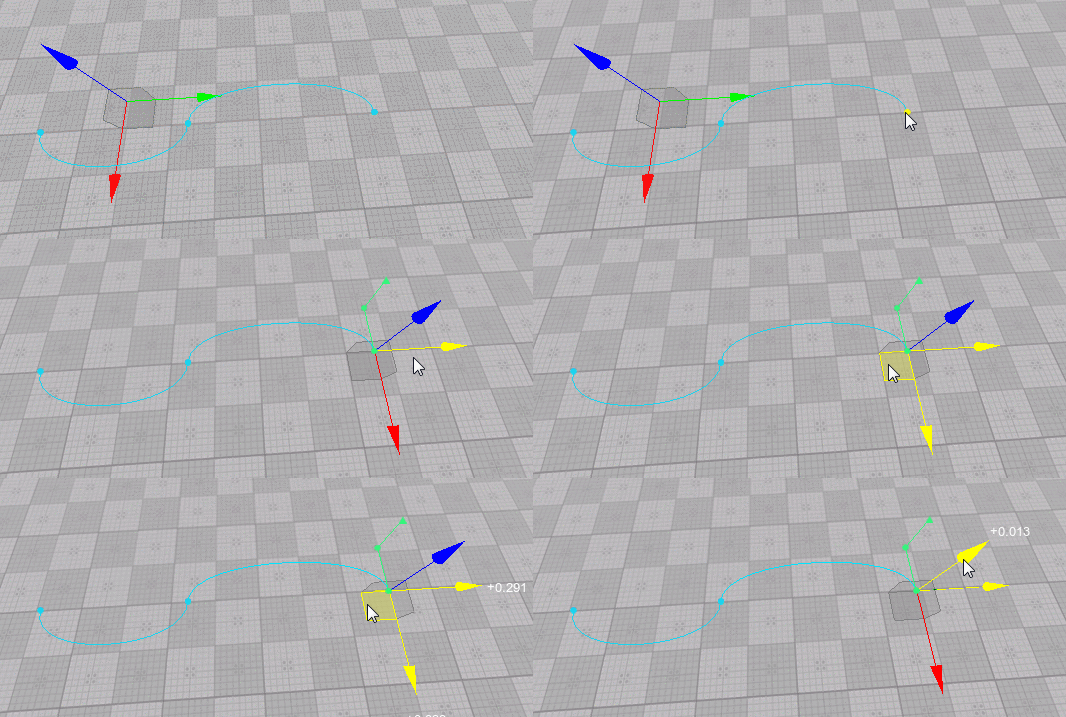
You can also adjust the position of the selected point via the Spline Points section of the Parameters tab:您还可以通过Parameters选项卡的Spline Points部分来调整所选点的位置:

Adjusting Point's Tangent调整点的切线#
Tangents control the curvature of the spline segment. To adjust tangent at a point do the following:切线控制样条线段的曲率。要调整一点的切线,请执行以下操作:
- Select the World Spline Graph.选择World Spline Graph。
- Select the desired point (Move manipulator will appear).选择所需的点(将出现“移动操纵器”)。
- Select the desired tangent (in case the selected point is shared by multiple segments, several tangents will be displayed for it). As you select a tangent the Move manipulator appears next to it.选择所需的切线(如果所选点被多个线段共享,则将为其显示多个切线)。选择切线时,其旁边将显示“移动”操纵器。
- Use the Move manipulator as you would do to move a node (the form of the corresponding segment will change).使用移动操纵器,就像移动节点一样(相应段的形式将改变)。

Adjusting Point's UP Vector调整点的UP向量#
Up vector controls orientation of nodes placed along the spline segment. To adjust tangent at a point do the following:上矢量控制沿样条线段放置的节点的方向。要调整一点的切线,请执行以下操作:
- Select the World Spline Graph.选择World Spline Graph。
- Select the desired point (Move manipulator will appear).选择所需的点(将出现“移动操纵器”)。
- Select the desired UP vector (in case the selected point is shared by multiple segments, several UP vectors will be displayed for it).选择所需的UP向量(如果所选点被多个线段共享,则将为其显示几个UP向量)。
- Switch to Rotate manipulator and use it to adjust the desired angle as you would do to rotate a node (the orientation of nodes placed along the corresponding segment will change).注意You'll be able to see the effect only when a node is assigned to the corresponding segment.切换到“旋转操纵器”并使用它来调整所需的角度,就像旋转节点一样(沿着相应线段放置的节点的方向会改变)。You'll be able to see the effect only when a node is assigned to the corresponding segment.You'll be able to see the effect only when a node is assigned to the corresponding segment.注意You'll be able to see the effect only when a node is assigned to the corresponding segment.仅当将节点分配给相应的线段时,您才能看到效果。
- Use the Move manipulator as you would do to move a node (the form of the corresponding segment will change).使用移动操纵器,就像移动节点一样(相应段的形式将改变)。

Merging Points合并点#
Sometimes it might be necessary to merge certain points (e.g. to close a spline). To merge two or more points into one do the following:有时可能需要合并某些点(例如,关闭样条线)。要将两个或多个点合并为一个,请执行以下操作:
- Select the World Spline Graph.选择World Spline Graph。
- Select points you want to merge with a region selection tool or one-by-one while holding the Shift key pressed.按住Shift键,选择要与区域选择工具合并的点或一对一地选择点。
- Right-click on a point you want to merge selected ones into and choose Merge To This Point.右键单击要合并所选点的点,然后选择Merge To This Point。
- All points will be merged into one shared by the segments, to which the merged points belonged.所有点将合并为合并的点所属的线段共享的一个。

Deleting a Point删除点#
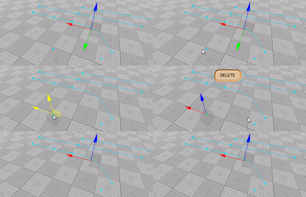
To delete point(s) of the spline graph do the following:要删除样条图的点,请执行以下操作:
- Select the World Spline Graph.选择World Spline Graph。
- Select point(s) you want to delete with a region selection tool or one-by-one while holding the Shift key pressed.按住Shift键,使用区域选择工具或一对一地选择要删除的点。
- Press the Del key.按Del键。
Managing Segments管理细分#
Adding a New Segment添加新细分#
To add a new segment to the spline graph do the following:要将新线段添加到样条图,请执行以下操作:
- Select the World Spline Graph.选择World Spline Graph。
- Select the starting point for the new segment to be added (Move manipulator will appear).选择要添加的新段的起点(将显示“移动操纵器”)。
- Press and hold the Shift key and use the Move manipulator to position the ending point of the new segment.注意To create a straight segment, you should drag the manipulator in the direction of the tangent at the starting point.The new added segment uses all settings (assigned nodes, placement modes and parameters) of the previous one.按住Shift键,然后使用“移动”操纵器定位新线段的终点。
- To create a straight segment, you should drag the manipulator in the direction of the tangent at the starting point.To create a straight segment, you should drag the manipulator in the direction of the tangent at the starting point.
- The new added segment uses all settings (assigned nodes, placement modes and parameters) of the previous one.The new added segment uses all settings (assigned nodes, placement modes and parameters) of the previous one.
注意- To create a straight segment, you should drag the manipulator in the direction of the tangent at the starting point.要创建直线段,应在起点处沿切线方向拖动操纵器。
- The new added segment uses all settings (assigned nodes, placement modes and parameters) of the previous one.新添加的细分受众群使用上一个细分受众群的所有设置(分配的节点,放置模式和参数)。
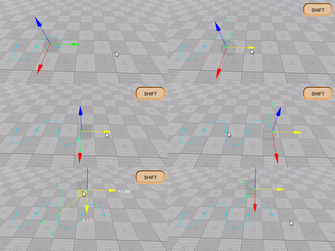
You can also clone segment(s) by selecting them and moving with the Shift key pressed, or pressing Ctrl + D and placing the clone with the Move manipulator.您也可以通过选择分段并按Shift键移动来对其进行克隆,或者按Ctrl + D并使用“移动”操纵器放置克隆。
Deleting a Segment删除段#
To delete segment(s) of the spline graph do the following:要删除样条图的线段,请执行以下操作:
- Select the World Spline Graph.选择World Spline Graph。
- Select segment(s) you want to delete with a region selection tool or one-by-one while holding the Shift key pressed.按住Shift键,使用区域选择工具或一一选择要删除的段。
- Press the Del key.按Del键。
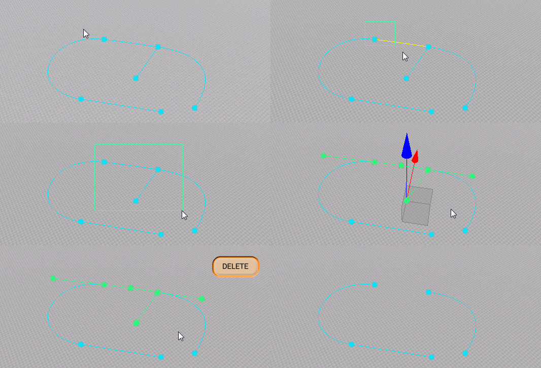
Managing Source Nodes管理源节点#
As described above, a single or a set of source nodes can be assigned to each point or segment of the spline graph.如上所述,单个或一组源节点可以分配给样条图的每个点或线段。
Workflow for Segments区隔的工作流程#
To assign a source node to selected segment(s) do the following:要将源节点分配给选定的段,请执行以下操作:
- Select the desired segments(s).选择所需的段。
- Click Add Node in the Parameters tab.在Parameters选项卡中单击Add Node。
- In the window that opens, select the required node and click OK.注意Source nodes to be assigned to segments and points are stored in *.node files. The node file should contain a Static Mesh, Skinned Mesh, or Projected Decal as a root node.在打开的窗口中,选择所需的节点,然后单击OK。Source nodes to be assigned to segments and points are stored in *.node files. The node file should contain a Static Mesh, Skinned Mesh, or Projected Decal as a root node.Source nodes to be assigned to segments and points are stored in *.node files. The node file should contain a Static Mesh, Skinned Mesh, or Projected Decal as a root node.注意Source nodes to be assigned to segments and points are stored in *.node files. The node file should contain a Static Mesh, Skinned Mesh, or Projected Decal as a root node.要分配给线段和点的源节点存储在*.node文件中。节点文件应包含Static Mesh, Skinned Mesh或Projected Decal作为根节点。
For each of the source nodes assigned to the selected segment(s) the following settings are available for adjustment via the Parameters tab:对于分配给所选段的每个源节点,以下设置可通过Parameters选项卡进行调整:

| Node | Path to a *.node file containing a source node.包含源节点的*.node文件的路径。 |
|---|---|
| Forward Axis | Defines which axis of the source node is to be oriented along the spline.定义将沿样条线定向源节点的哪条轴。 |
| Placement Mode | Type of objects to be generated. One of the following:
注意 This mode is the most performance-friendly.Tiling - multiple instances of the source node are placed along the segment. The number of instances is determined by the sizes of the segment and the source node and the value of the Gap parameter.Adaptive - a combination of the previous two resulting in multiple instances of the source node placed along the segment. Some of these instances may be stretched depending on segment's curvature.要生成的对象的类型。以下之一:
This mode is the most performance-friendly.This mode is the most performance-friendly.
|
| Adaptive Threshold | Determines how much a source node's instance can be stretched in the Adaptive placement mode to cover the whole length of the segment. 注意 Available for Adaptive placement mode only.确定在Adaptive放置模式下可以将源节点的实例拉伸多少,以覆盖该段的整个长度。Available for Adaptive placement mode only.Available for Adaptive placement mode only. 注意 Available for Adaptive placement mode only.仅适用于Adaptive放置模式。 |
| UV Tiling | Enables tiling of the source node's textures.启用源节点纹理的平铺. |
| Gap | Defines the gap (in units) between the adjacent instances on the source node for the Tiling placement mode. 注意 Available for Tiling placement mode only.为Tiling放置模式定义源节点上相邻实例之间的间隔(以单位为单位)。Available for Tiling placement mode only.Available for Tiling placement mode only. 注意 Available for Tiling placement mode only.仅适用于Tiling放置模式。 |
Workflow for Points积分工作流程#
To assign a source node to selected point(s) do the following:要将源节点分配给选定的点,请执行以下操作:
- Select the desired point(s).选择所需的点。
- Click Add Node in the Parameters tab.在Parameters选项卡中单击Add Node。
- In the window that opens, select the required node and click OK.
注意For a junction point to behave properly an ObjectMeshSkinned node should be assigned, and the number of its bones should correspond to the number of spline segments connected to this point.在打开的窗口中,选择所需的节点,然后单击OK。For a junction point to behave properly an ObjectMeshSkinned node should be assigned, and the number of its bones should correspond to the number of spline segments connected to this point.For a junction point to behave properly an ObjectMeshSkinned node should be assigned, and the number of its bones should correspond to the number of spline segments connected to this point.注意For a junction point to behave properly an ObjectMeshSkinned node should be assigned, and the number of its bones should correspond to the number of spline segments connected to this point.为一个交界处为使点正常运行,应分配一个ObjectMeshSkinned节点,其骨骼的数量应与连接到该点的样条线段的数量相对应。
For each of the source nodes assigned to the selected point(s) the following settings are available for adjustment via the Parameters tab:对于分配给选定点的每个源节点,以下设置可通过Parameters选项卡进行调整:
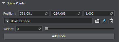
| Node | Path to a *.node file containing a source node.包含源节点的*.node文件的路径。 |
|---|---|
| Variant | There is a number of possible variants for a junction. This slider enables you to choose the one that fits best. 注意
This parameter affects only the source nodes representing junctions (ObjectMeshSkinned).This parameter affects only the source nodes representing junctions (ObjectMeshSkinned).
注意
This parameter affects only the source nodes representing junctions (ObjectMeshSkinned).此参数仅影响表示结点(ObjectMeshSkinned)的源节点。
|
Junctions交界处#
Junctions should interact with all entering segments properly providing seamless transitions. For this puprose ObjectMeshSkinned source nodes are used.交界处应与所有进入的路段正确互动,以提供无缝过渡。为此,使用了ObjectMeshSkinned个源节点。
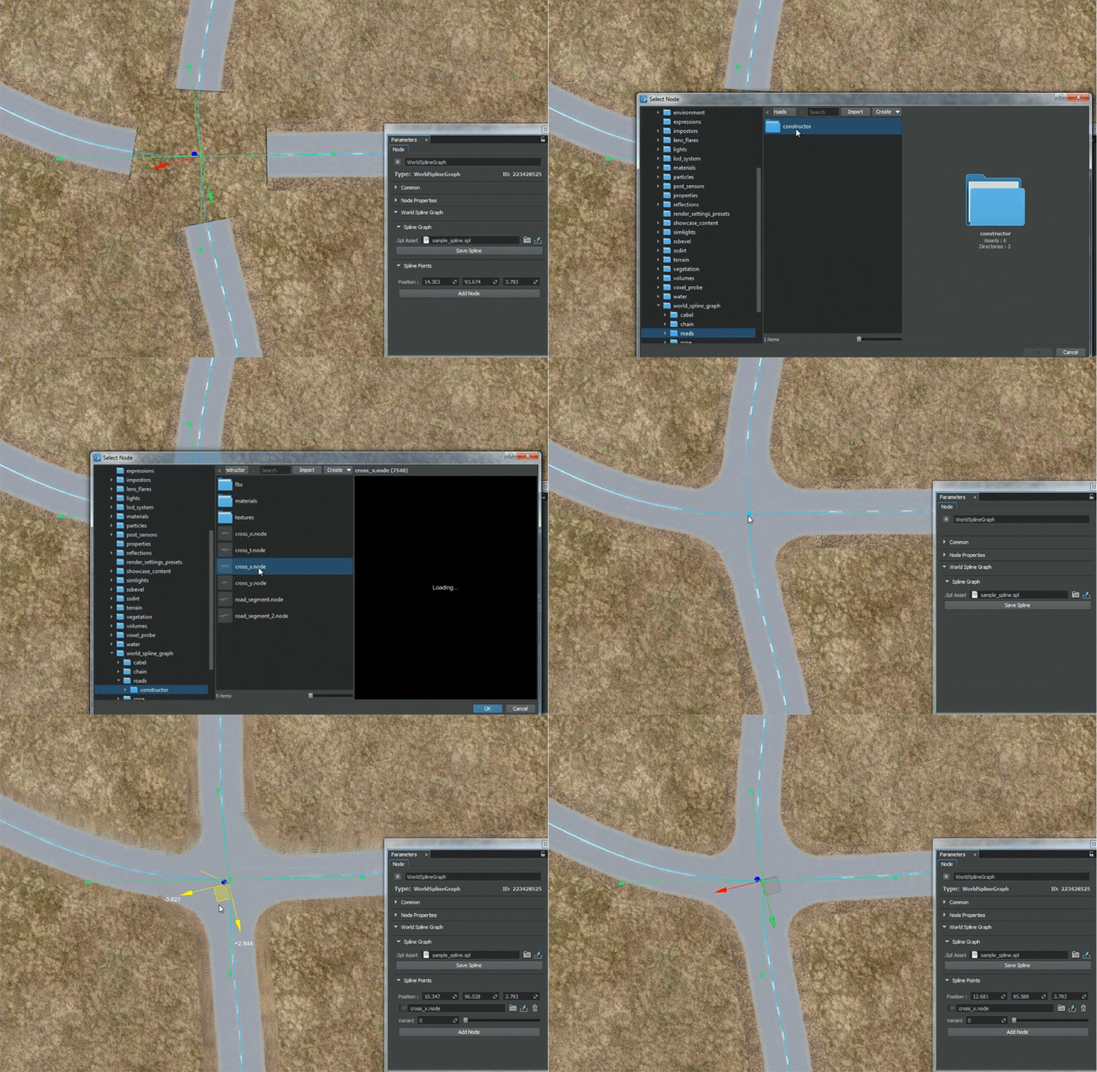
Source nodes to be used for junctions must comply with the following requirements:用于结点的源节点必须符合以下要求:
- Joints of a junction in the UnigineEditor must have their Y axes oriented from the center of the junction to the edges of the corresponding branches.UnigineEditor中接合点的关节必须使其Y轴从接合点中心到相应分支的边缘。
- Outer joint of each junction’s branch must be placed exactly at the center of its outer edge, weights for outer vertices of the branch must be maximal for the outer joint (i.e., outer vertices of the branch are affected only by the outer joint).每个结点的分支的外部关节必须正好位于其外部边缘的中心,分支的外部顶点的权重必须对于外部关节最大(即,分支的外部顶点仅受外部关节影响)。
- As junction and segment are represented by separate meshes, textures and their UV maps must ensure seamless junction-segment and segment-segment transitions.由于接合点和线段由单独的网格表示,因此纹理及其UV贴图必须确保无缝的接合线段和线段段过渡。
- A segment may have junctions at both of its endpoints, Therefore the texture used for the segment must be symmetrical, at least its edges.一个段的两个端点可能都具有连接点,因此用于该段的纹理必须对称,至少其边缘必须对称。
- Specific requirements for roads:
- A junction as well as a road segment must be represented by a pair of meshes (embankment and the road itself). Embankment mesh is used for smooth blending with terrain surface. Just enable the Terrain Lerp state for the material assigned to embankment.A junction as well as a road segment must be represented by a pair of meshes (embankment and the road itself). Embankment mesh is used for smooth blending with terrain surface. Just enable the Terrain Lerp state for the material assigned to embankment.
- To ensure correct deformation of segments and junctions triangulation for the road and embankment must match. This prevents penetration of meshes into each other when moving spline points up and down.To ensure correct deformation of segments and junctions triangulation for the road and embankment must match. This prevents penetration of meshes into each other when moving spline points up and down.
- A junction as well as a road segment must be represented by a pair of meshes (embankment and the road itself). Embankment mesh is used for smooth blending with terrain surface. Just enable the Terrain Lerp state for the material assigned to embankment.路口和路段必须用一对网格(路堤和道路本身)表示。路堤网格用于与地形表面平滑融合。只需为分配给路堤的物料启用Terrain Lerp状态即可。
- To ensure correct deformation of segments and junctions triangulation for the road and embankment must match. This prevents penetration of meshes into each other when moving spline points up and down.为了确保路段和路口的正确变形,道路和路堤的三角剖分必须匹配。这样可以防止在上下移动样条线时使网格相互渗透。

Exporting World Spline Graph导出世界样条图#
World Spline Graph works well as a tool for object placement and deformation, but due to some technical issues, it is difficult to use it in final applications as the resulting object. Therefore, as soon as the object arrangement is final, it is required to export the spline graph to the .mesh or .fbx file.World Spline Graph 作为对象放置和变形的工具效果很好,但是由于一些技术问题,很难在最终应用程序中将其用作生成的对象。因此,一旦对象排列完成,就需要将样条图导出到 .mesh 或 .fbx 文件。
To export World Spline Graph, right-click it in the World Nodes hierarchy, select Export to and a preferable option:要导出 World Spline Graph,请在 World Nodes 层次结构中右键单击它,选择 Export to 和一个更可取的选项:
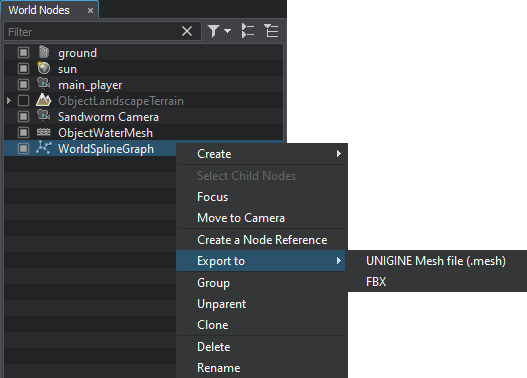
The export operation produces unique geometry that you can use in your projects like any other model without any additional restrictions.导出操作会生成独特的几何图形,您可以像使用任何其他模型一样在项目中使用这些几何图形,而不受任何额外限制。
Limitations限制#
Due to the nature of the mesh, there will be visual artifacts connected with the float precision, if World Spline Graph is exported to a very big object (around 10,000 m from the origin to either side). We recommend splitting such big objects to smaller ones.由于网格的性质,如果将 World Spline Graph 导出到非常大的对象(从原点到两侧大约 10,000 m),则会出现与浮点精度相关的视觉伪影。我们建议将这些大对象拆分为较小的对象。
A problem may also arise if World Spline Graph, though being not very big, is located very far from the origin (around 10,000 m and further). In this case we advise exporting it to FBX without storing pivot (the Save root transform option should be disabled), or resetting the World Spline Graph position to origin before exporting it to Mesh.如果 World Spline Graph 虽然不是很大,但距离原点很远(大约 10,000 m 甚至更远),也可能会出现问题。在这种情况下,我们建议在不存储枢轴的情况下将其导出到 FBX(应禁用 Save root transform 选项),或者在将其导出到 Mesh 之前将 World Spline Graph 位置重置为原点。
本页面上的信息适用于 UNIGINE 2.19 SDK.

