Calibration Grid
SpiderVision has the calibration grid that can be enabled to align projections in such a way that the connection between them is seamless and the displayed image is not distorted. When the calibration grid is enabled, you don't see the rendered image, but see the grid. Using this grid, you can use the projection setup features to easily align projections.
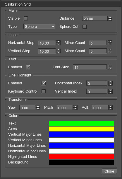
The Calibration Grid setup window is available via the menu: Tools -> Calibration Grid.

The following groups of calibration-related options are available:
| Main settings controlling the general view of the calibration pattern. | |
| Visible |
Toggles displaying the calibration pattern on the projection. |
|---|---|
| Distance |
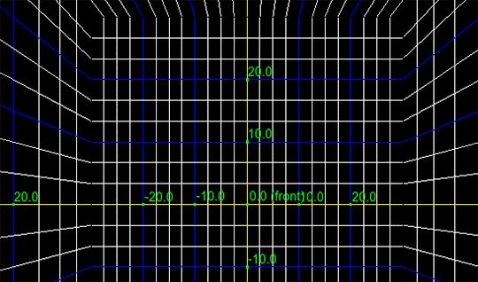
Distance from the camera to the grid. The difference is noticeable with the Box type of projection. |
| Type |
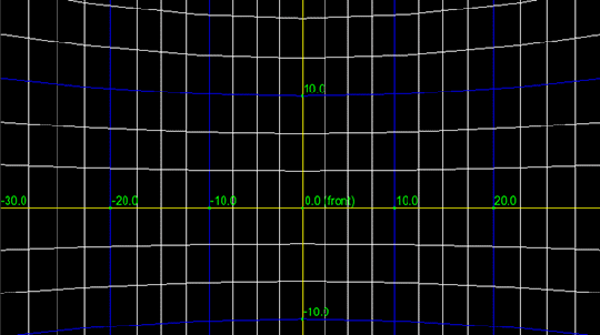
Type of the calibration pattern:
|
| Sphere Cut |
Allows hiding the top and bottom poles of the sphere for the Sphere-type calibration pattern. |
| Lines group of settings defines the distance between the lines and the number of minor (auxiliary) lines. | |
| Horizontal Step |
The distance between major horizontal lines. |
| Vertical Step |
The distance between major vertical lines. |
| Minor Count |
The number of secondary lines between the two neighboring major lines. Is set individually for vertical and horizontal lines. |
| Text group of settings allow enabling the text indications on the calibration grid and defining their size. | |
| Line Highlight group of settings configures highlighting of one horizontal and one vertical line. | |
| Enabled |
Toggles the highlighting on and off. |
| Horizontal/Vertical Index |
Index of the line that is to be highlighted. The lines are invisible, when their indices are set to zero. |
| Keyboard Control |
When enabled, you can change the highlight index using the keyboard:
|
| Transform group of settings allow transforming the grid along the vertical, transverse, and longitudinal axes. Only the grid is transformed, the projected image is not transformed. | |
| Color | Select colors for corresponding elements of the grid. |
The information on this page is valid for UNIGINE 2.19 SDK.

